For a long time now I have observed
that some artists still have trouble getting a fundamental grasp of surface smoothing and
how to best use it to their advantage. Let us first go over what the Lightwave Manual has
to say on this subject:
Surface Smoothing
Smoothing causes objects
to appear to have smoothly rounded surfaces even though the object is composed of
flat-faced polygons. To do this, LightWave uses a technique known as
phong shading . If the edges of two smooth-shaded polygons share vertices
(points), they appear as one continuous, curved surface. The shared edge between them is
no longer visible.
Okay we understand the
basic premise of this - it makes our surface look smooth - same as when we flip from flat
shade view to smooth shade view in modeler in the open GL preview view
port.
now the manual goes on to explain
smoothing thresholds:
Smooth
Threshold
By default, LightWave
will not smooth across two polygons if the angle between them is 90 degrees or sharper,
unless you adjust the Smooth Threshold . This value adjusts the range of the smoothing
function; it defines the angle beyond which LightWave will not smooth over the seam
between adjoining polygons. The angle is measured using the surface normal's of the
adjoining polygons. If this angle is less than the Smooth Threshold , the surfaces are
rendered smoothly. The default of 89.5° assures that any surfaces at right angles (90°)
or greater to each other are not smoothed.
Sometimes, due to the
way an object is modeled, you may get unexplained rendering errors on smoothed surfaces.
Try increasing the Smoothing Threshold to correct for such errors. We recommend using
smaller increases first, although for extreme displacement-mapped objects, you may try
fairly high values if rendering produces a mixture of jagged and smoothed
results.
Ok so what does this actually mean? Lightwave will automatically
place a default smoothing angle of 89.5 degrees to a surface when you
create it - if you actually activate smoothing. What this means to us is this:
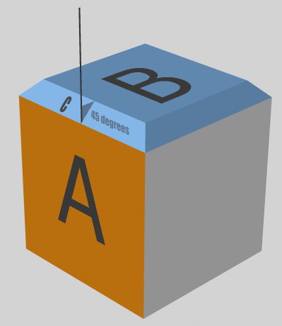
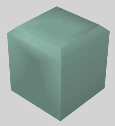
..lets take for example a perfect box; the angle is measured
between adjacent faces - so in the figure below we can clearly see that the angle between face
A and Face B is obviously 90 degrees as it is a perfect box.
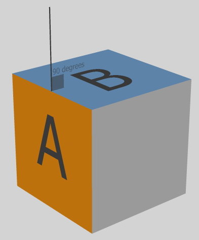
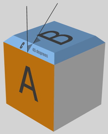
in reality what is happening is that LW is studying the surface
normal's -
they are the little lines that point away from your faces
and measuring the angle between them like this:
this is deemed as being 90 degrees and is the basis on what
smoothing threshold will be acted upon.
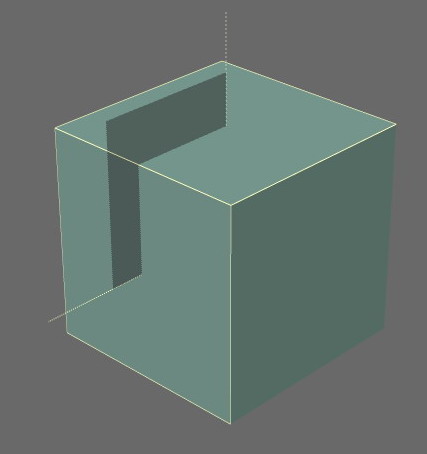
Smoothing is turned on for this surface and the angle is
LightWave's default of 89.5 = in other words half of a degree less than the angle the faces
share and the smoothing effect is obviously nice and sharp edged like so:
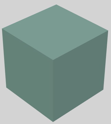
but look what happens when we make the surface smoothing
90 degrees instead:
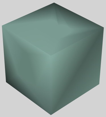
Lightwave understands that the surface smoothing threshold has
been set to 90 and that the angles between the adjacent faces is 90 and therefore it tries it
damned hardest to smooth those edges and the result is quite ugly indeed.
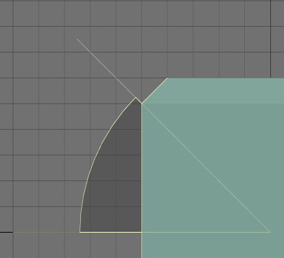
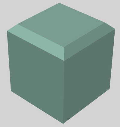
We can observe this effect even with 45 degree faces. Lets take
our box again and this time bevel the top edge with an equal Inset and Shift amount which will
give us a perfect 45 degree chamfer angle like so:
the smoothing calculations will now no longer be carried out between faces A and B as we
have created a new face - C. The smoothing is now worked out as A relative to
C, and then C relative to B. The angle between A and C is 45 degrees. Obviously the angle
between C and B is also 45 degrees...
again in reality what is actually happening is this-- Lightwave is
studying the surface normal's and making calculations based upon them - my diagrams just offer
an alternative way of interpreting what is happening.
now if we set our smoothing threshold to 44.99 (and yes LW can be just that precise) we can see nice sharp defined
edges
but the second we add that missing 100th of a degree we get this:
as you can see LW is now trying to smooth those edges yet again.
Hopefully now you understand the concept of how smoothing is applied to edges of adjacent
faces. But I hear you wondering exactly what does this have to do with anything in
particular?
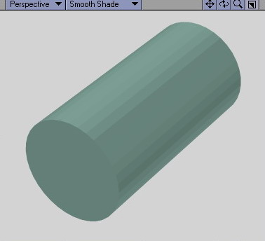
Let's turn our attention to a cylinder. This cylinder has 36
sides. Simple maths tells us now that the angle between adjacent surfaces must be 10 degrees
and sure enough with a smoothing threshold set to 9.99 degrees we get a flat shaded effect to
our cylinder
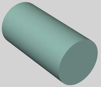
and yet again if we add that missing 0.01 of a degree we
still get a flat shaded look and I put this down to the smoothing engine
not being able to decide whether to smooth the edge or not -- as we are being
extremely precise here - but if I add just another 0.01 to the setting to
make it 10.01 there is no doubt in LW's mind anymore and it smoothes the
surfaces:
OK we are really getting a firm grasp on this now,. but let's
take a look at a problem that very commonly occurs for a modeler when they are making detailed
objects.
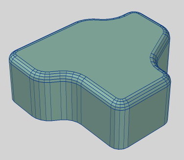
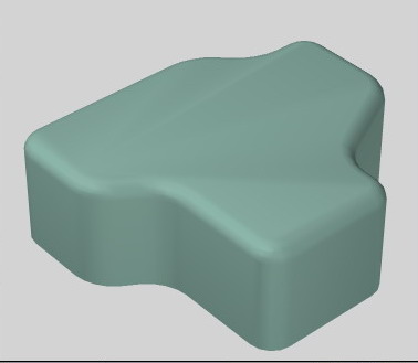
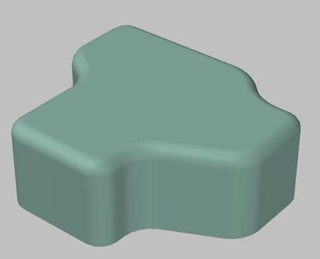
we've made a fairly complex object and we now need to smooth our
rounded edges - the usual practice here is to keep upping the threshold until we see our
rounding become smooth:
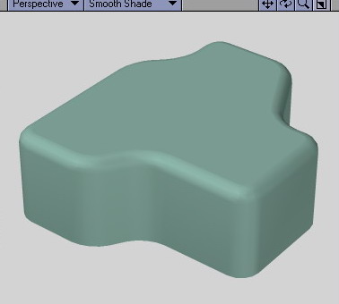
and then we notice the problem - the second
we get our rounded edges looking smooth (in this case it was 25
degrees) we have begun to get smoothing errors on our top flat
surface.
Why? Well the answer is simple - because our rounded edge
required a threshold of 25 degrees to smooth all our sides - the threshold angle between to the
top most flat face and the next adjacent face falls well below that threshold too --and thus
Lightwave will attempt to smooth it as well. The problem is - we do not want that to
happen.
What can we do to stop this problem?
The power of the INSET BEVEL
we can eliminate this smoothing threshold error by creating a
small bevel inset to the top polygon face. By using a inset of about 1mm or whatever is
necessary we can get the desired result..
Why does this work? Well when you create an inset you essentially
are just making a smaller version of the polygon that sits within the original shape sharing
the same plane. The angle between edges of the parent face and the new inset
face is now 0 degrees and therefore as the normal is facing the exact
same direction as it's adjacent polygon and the angle is zero - well no
smoothing is required at all despite what the threshold is set to ..because at the end of the
day a threshold of zero degrees is no smoothing at all isn't it? 
NOW Richard Brak the guy who designed the
rounder plug-in was well aware of this and even gives you the option of
inserting these inset divisions right there in the plug-in!
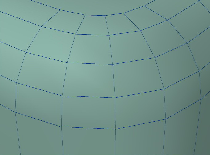
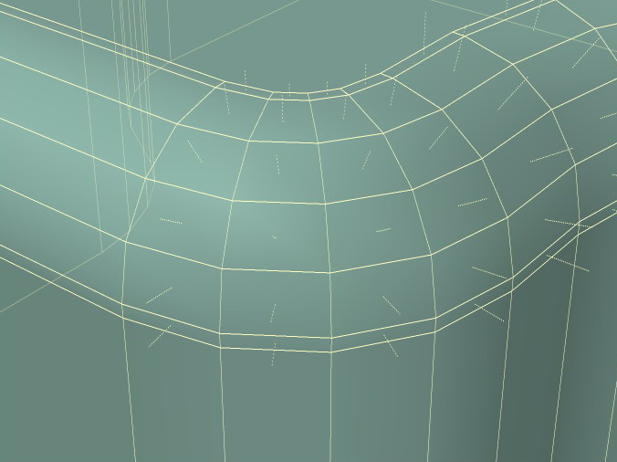
from our previous example here is the rounderised top face of our
object along with the resultant smoothing errors that come with it....
let's now have a close look at the edges involved:
now have another look at the rounder numeric panel options and
you will see a OGL POLY TAB
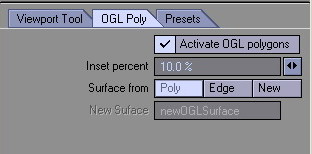
just by activating it and using that setting we get this - a
double inset before and after the rounding..
with the result being ultimately now - no more smoothing
errors...
If you are using Vertibevel similar effects
can be achieved by adding your beginning and end inset manually along these lines..
even for strange extrusions like this one they can be
added:
Quite often I observe that people
are having trouble with their smoothing. They try to combat it by using the old cut and paste
technique - which removes faces completely from their neighbours and thus takes smoothing
totally out of the equation. Often that technique is used and all threshold are left at the
default of 89.5 degrees.
Sometimes you can tell that some one
has had a problem smoothing an object and has settled for less of a threshold than is required
to eliminate the problem we have observed with the rounder example - the result of this is that
edges that have been rounded and need to therefore be smooth -- now begin to look
faceted. In the vast majority of cases as that is needed to solve this common
glitch is an Inset to the face that
is giving you the grief!
Crucially though it is also
important to remember not to get carried away with this technique - because if for example you
are making an object that consists of mainly flat faces and sharp 45 degree chamfers then the
use of the start and finish insets are completely un-required as smoothing
thresholds will handle everything there adequately enough. an example would be say the main
body of Tie Fighters wing. It will only add unnecessary polygon divisions in that
instance!
Even taking all of this into account
there is often a time when you have to break up an object into 3 distinct surfaces. For example
when I am working on a bank of Nurnies for a piece of machinery - they will commonly consist of
flat edged objects - flat edged objects with rounded edges and cylindrically based
objects.
I will often have to divide these
Nurnies into 3 distinct groups - those that are surfaced with none or very little threshold on
smoothing - those that need moderate smoothing and those that need lots of smoothing. This is
often the only way and yes it does call for 2 extra surfaces to your mesh for a certain area
that was previously required but often the payoff is that visually it is very much worth the
effort.
Master your smoothing angles and you
will soon discover that they are indeed your greatest friend.

 Facebook
 Twitter