|
VORLON ENERGY BEAMS
|
The techniques for making these beams? - well I made them up for my own
purposes - but hopefully they can help others out - this is one of the things with
Lightwave - you will find yourself innovating a lot as you learn more - so I really
recommend getting a good notebook and making a note of things as you learn them - because
people you won't remember them all! Trust me on that 
During the course of this tutorial we'll be flitting back and forth between
Layout and Modeller - so if you're following it - open both programs.
We are trying to replicate the energy convergence when the Vorlon weapon's
fire - so we need a basis to work with so load up the VORLON dreadnought into Modeller.
Then switch to another layer - nothing in the background and we'll concentrate on making
some beams:
First of all make a nice squiggle spline curve - as
explained in the Rail Extrude tutorial. Something like this:
|
|
|
Now follow these steps :
Copy this curve to another layer
In one of the layers where the curve is - run the Points2polys plug-in in the
tools section then delete all but the top most polygon.
With this layer as the foreground - select the curve as the background and then run rail
extrude with default values
you'll get a nice curvy beam like this
|
|
|
Now make 2-3 copies of this beam and paste to different layers
- rotate them along the Y axis and/or rotate them around the X axis to create
multiple beams - then when you're happy with placement weld the topmost points together
and then the same for the bottom and ensure they are on the x=0 position
like so
|
|
Right the beam is done - now we have to size the object to the dreadnought
-
|
Next we have to put the Dreadnought into the picture - get yourself a
pen/pencil and a piece of paper. We know the beams run diagonally across the boom
ends - so we need to make some measurements.
At this point I really do recommend that you get hold of the Supersize
Plug-in. I use it for everything I model - it allows you to set a dimension on one
axis and then scale the other dimensions to fit - or to simply affect one axis
measurement at a time - it is easy to use and I would say almost a necessity - it's
freeware - so go get it!
SUPERSIZE - GET IT HERE!!!
--------------------------------------------------------------------------------
Using the Dreadnought booms as reference take the following measurements -
and then using Pythagoras work out the length of the
diagonal.
|
|
|
By my calculations A=282m, B=192m. Therefore using Pythagoras - C=
square root of A Squared + B Squared , which equals 341.16m which sounds about
right - so now using Supersize (or another method) make the beams approx. 341.16
m High along the Y axis - scale the other two axes as well for now.
Now position the object in the right place at the ends of the booms (do
this with the dreadnought in the background for reference) and then proceed to rotate
about the z/x axis intersection until the ends of the objects touch the relevant parts of
the booms - make a note of the angle - in the bottom left of the screen - then undo this
action. I made it 56 degrees. At this point save this object as
ZAP
|
|
Now we go into layout:
In layout - load the dreadnought and the Zap object - the zap
will load into the correct place
Create a Null Object
Parent the Zap to the Null
Parent the Null to the Dreadnought
In Modeller ascertain the Zap's top most points position along the Z axis - mine was
-500m
Using that figure move the zaps pivot point in layout using the numeric requester
to the same position on the Z axis.
Bank adjust the Zap's Null to 56 degrees, then lock all adjusters - move - rotate etc..
If you now select the Zap object in layout and lock all position
adjusters apart from Heading; you'll find that you can rotate the Zap around it's own
axis for animation's.
Repeat this process again for the other Zap - but remember then angle is now -56 degrees
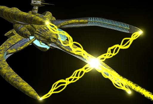
All you need to do now is add a lens flare at each Zaps origin on the booms
and 2 nice fat ones at the center of the zaps - where they intersect.
Like so:
|
|
|
Here are my settings for the flares
Boom Flare - energy Origin:
RGB: 255 / 255 / 0
Light intensity - 80%
Intensity Falloff - 150m
Shadow type - Off
Flare Settings:
Flare intensity - 120%
Fade with distance 200m
Fade off screen
Central glow
Random streaks - streak intensity 2% / density 50% / sharpness - 6
Beam Intersection Flares:
same as Boom flare but: Flare intensity = 250% and Intensity Falloff =
400m
I turned off Specular and diffuse for these lights - but that's up to you
Surface Shader settings for the beams: RGB 255 / 255 / 0 ---- Glow at
95% or higher.
This what it looks like:
|
|
|
|
Need help detailing your spaceships? Have to make a cityscape fast? Need
to fill any area with random believable detail?
The
Ultimate Greeble & Nurnie Collections will make light work of any of your Projects! Check them out now!

|
 Facebook
 Twitter