Polygons - Trigons - Quads - N-Gons - Tripling - NON Planar - Nurbs - Freezing - what does it all mean?? 

The theorems and practices I am about to outline are common place and widely used as datum's in the industry - I am by no means suggesting these are the holy grail of doing things - but they have served me well in a production environment for well over 10 years - you decide for yourselves if that is a pedigree worth listening to.

So - what do all these terms mean and how and why do we use them?

Let's first deal with Planar. What exactly does planar mean in a 3D sense? how does the dictionary define the word planar?

–adjective: [1] of or pertaining to a geometric plane. [2] flat or level

So planar means flat - pretty simple you would think eh? Not so really. When it comes to polygons - flatness is a holy grail. You see a perfectly flat surface - and in 3d terms, a surface is an 'imaginary' skin defined by a geometric shape comprised of points that define a set of straight edges that form a border i.e. a polygon - yes a surface is cooked up by the render engine using the control points and edges of the polygon to define it's shape in 3d space. If those points all occupy the same plane then the resultant surface will be perfectly flat and the render engine has a very easy time of it calculating all that it needs to know when producing the end result.

In fact - especially in Lightwave and many other applications (if not ALL of them) - when it comes to render time the maths happening in the background converts all polygons that comprise a model into triangles to enable the calculations to be made efficiently and properly - So why not - you may ask - do we not model in triangles in the first place then?

Let's first address why a triangle is the preferred ideal - you see, a triangle by its very nature mathematically; can never be anything except flat. Period. It does not matter what shape that triangle is - it will always be flat. So the render engine makes everything triangles to ensure that everything with regards to the surfaces created is rendered properly. This leads us to another question - if it does this all the time anyway why then do we get render errors in our objects sometimes if the engine has made everything "proper" so to speak?

This arises because we don't always model in triangles - in an ideal mathematical world we would - but it is a very impractical way to go about things when it comes to designing and creating - it's not a problem for a computer - but to the human mind it's an unnatural way to do things especially when shapes get very complex - the resultant mass of triangles makes it very difficult for a modeler to perceive what he is doing as opposed to using polygons with more than three sides.

Modelers tend to work with quads and n-gons so what are these?

A quad - as it name would suggest is a polygon composed of four sides - a square or rectangle then if you will. as you can see in the next diagram - this quad is flat:

secretly come render time though this will happen:

It will be converted into two triangles - why then does it do this? Well it's because a quad is by no means guaranteed to be planar because the quad could look like this:

As you can see two points that have been moved have now made this quad blatantly NON Planar - or NOT FLAT. And the only way the render engine can determine how to properly construct the surface is to triple it - this is the process for making a polygon into triangles or 3 side polygons - which remember can never be anything other than flat. the result would ultimately be something along the lines of this:

but depending on how the render engine is feeling it could also decide to make it like this:

As you can see there are two possible solutions in parsing this non planar quad, each with quite drastically different results really - one solution may be desired and the other may not - and this is just a quad folks! - We haven't even delved into the arena of N-Gons yet!


So we've seen what can happen with naughty quads - now what about N-Gons? Firstly what is an N-Gon? An N gon is an annotational way of describing a polygon with more than three sides where N is the variable that denotes the amount of sides. Theoretically a Quad is a N-GON but in the trade we tend to call them quads basically and refer to anything with more than 4 sides as n-gons.

So this is a typical n-gon:

now remember come render time we will inevitably have this thing tripled in the background anyway but crucially the number of solutions that the render engine can come up with is now a lot greater: Typically it would be somewhere along these lines:

about 4 triangles is what we can expect here but the number of ways these four triangles can be arranged is quite high - think about the different ways those four triangles can be arranged? - it's quite a lot and it gets worse when we go higher with our sides or edges count:

Think about the number of possibilities of tripling this n - gon - the tripled one shown is just an example of many that the tripling engine could have come up with.

But let's get back to the triangle issue come render time. If as we now know everything gets tripled come render time- should we not work with triangles in the first place? Well take a look at the image directly above - would you prefer to work with the polygon on the left or the one on the right? Generally I bet you'll say the LEFT one and the reason is because it's easier - imagine a big complex mesh plastered with triangles - it gets very difficult to work with after a point. Mathematically - the computer cares very little - but our eyes and brain soon get taxed with it. Which is why I posit we were given the ability to NOT do it in the first place.

Now generally polygons that are deemed PLANAR, Lightwave will usually not ever have a problem with determining the correct shape of the surface when it comes to render time. However: some polygons will be flagged as non-planar and the reason they get flagged is that the likelihood of the render engine not being able to consistently come up with the correct solution for the shape of that surface has now risen to an unacceptable level, and needs addressing. But herein lies a problem - you see mathematically nothing that has more than three sides is truly planar! So why doesn't everything that isn't a triangle get flagged as non-planar when we look in modeler stat's window then?

Well the program creators gave us a planar tolerance setting. The render engine is fairly clever and usually gets the hang of non planar polygons up to a certain level, but after then as we have already mentioned; the render engine will have problems and flags the polygons that it may have issues with.

The tolerance for planar polygons is set in the options panel of Modeler and is called the flatness limit - the default setting is 0.5% this shape at 0.5% reports no non planar polygons:

however if we now drop the flatness limit to a true math level of detection of 0.00% look what happens:

as you can see everything that wasn't a triangle gets reported now as non planar!

Now the default flatness limit of Modeler at 0.5% can sometimes be a little too forgiving - and I usually have mine set at 0.45% - this will flag non-planar's that I have found from experience do cause issues when it comes to render time and I then address them and make them as planar as possible to avoid these issues. 


So now we know a few things: Lightwave is fairly clever and most non planar's can quite comfortably be worked out by the render engine cleanly and consistently up to a certain point. At that point the solution of how the background process arranges the tripling or "fanning" as it's often called, could result in wildly differing surface shape solutions; which could cause problems come render time - especially in an animation where the shape of the non planar polygon could vary drastically throughout the animation itself.

The program designers have concluded that a good detection level of flatness is 0.5% to avoid most of these issues - like I have mentioned I prefer to use 0.45% myself.

Now as I have already mentioned we can avoid all these issues ourselves if we just tripled everything anyway - - but the point is we shouldn't have to, and that's why most of the tools available to us allow to not have to work that way. Now let's move onto another example:

This is the result of stenciling away a disc from a flat quad. Now come render time it will get tripled and the variations are large!

There's lots of ways to come up with the fanning solution here - but the point is we really do not have to worry about it - why? Well because our resultant polygon is FLAT. It really does not matter how Lightwave figures out the fanning as it will always produce the same result regardless as the polygon is flat enough for there never to be an issue with the shape of the surface. The only real reason to have it fanned is to make it look tidy for our own eyes. This shape was created in very simple steps - a box was drawn - then a disc and then it was stenciled away - a 3 step operation and fairly fast to carry out. There is another way to do it that makes a nice looking fan setup: It consist of starting with a circle - beveling out and then shaping into a square.


Now as you can no doubt agree this looks pretty indeed. It will also never cause the render engine any problems either - but crucially you can work out for yourself how many steps were required for this! And remember this polygon is FLAT! Like we have said before it doesn't matter how the fanning is resolved the end result will always be the same and the untidiness you will never actually ever see - it all happens in the background - invisibly. Crucially - do YOU want to work this way? You will become a very slow modeler and the probable likelihood of all your hard work is that some modeler some day will just hit "reduce polygons" in modeler and eliminate all your work in any case because in reality - it's simply not necessary for an inherently flat surface.

Figure out what would be involved in making this flat polygon using the second "tidier" method:

That said, I sometimes put a few slices in here to make it "look" a little tidier:

but it's not really necessary - truth be told.

DO EVERYTHING WITH NURBS THEN!! 

Now some people think that the way to get around the planar issues to an extent is to model exclusively with Nurbs. This however is an exercise in futility most of the time. But before we continue let's get a basic understanding of Nurbs in Lightwave and what they are.

They are essentially a way of modeling in high detail using a low polygon cage to control arrays of polygons and manipulate them into the shapes desired.

The size of the array of polygons used with this modeling method is controlled in the Modeler options panel using either the sub patch divisions setting or the catmull Clark level settings.

Let's look at normal sub patch for the moment. If you use a sub patch level of say 4 - then each quad you create (and you have to use either quads or triangles with this type of sub patch) will be controlling an array of 4x4 polygons or 16 polygons. You can see this by setting the perspective window to flat shaded to see an approximation of the resultant frozen mesh.

Usually the best setting to work with is about 6 and this will create an array of 36 Polygons for every sub patch quad you use:

Catmull Clark works differently - It uses different methods altogether and allows us to model with n-gons in sub patch mode

generally levels of 1, 2 ,3 and 4 in the catmull Clark level field results in arrays of 4, 16, 64 and 256 respectively per sub patch quad. As you will have noted CC levels vary greatly as they are increased when compared to normal sub patching.

But working in quads and sub patching is by no means a guarantee at all of polygons being planar. If we now look at the entire object I am using as an example, we will see there are a lot of resultant non planar polygons when it is frozen:

It is for this very reason that not only does Lightwave freeze a Nurbs mesh for every single frame but it also Triples every single resultant quad to guard against non planar issues. But much like antibiotics it is NOT discriminatory - it triples everything not just the ones that end up non planar - and for good reason. You see Nurbs meshes that are left as Nurbs mesh's in layout have usually been done so in order that they can be deformed.

This is crucial - a fluid organic shape changes all the time throughout an animation and the deformities vary from frame to frame - what may be non planar one frame when frozen may not necessarily be so the next frame and so on. So everything gets tripled - simply saves the hassle.

Lets look at this shape I'm using as an example: as a Nurbs cage it looks like this:

just 22 polygons exist here: But when frozen and tripled to mimic layout operations at a sub d level of 3 (layouts default) it becomes:

396 polygons. Now - most of the time in the industry layout is usually set to a display sub patch level of 1 and a render sub patch level of 6 which tends to give the best results for the vast majority of sub patch models and the result then is:

that's right 1,564 polygons! You really need to bear this in mind when creating sub patch meshes! 


You could be forgiven for thinking now that I do not like Nurbs! Ha hah - well sorry to disappoint you but I think Nurbs are great! They are brilliant modeling tools when required. But they must - like everything - be used with discretion and wisely.

Generally a Nurbs mesh should be left as a Nurbs mesh for layout if the final requirement is deformations within layout - i.e. character meshes - animal meshes etc..etc.. by their very nature they need to be Nurbs to be animated properly.

Sometimes also in my career some very fluidic organically shaped hard body models have been kept Nurbs to allow the animators some level of discretion when it comes to rendering. They can for example set the mesh to a render level of just 1 for background shots and then up it to say 6-8 the closer the mesh gets.

However 80-90 percent of the time additional surface detailing of such mechanical objects makes this method vastly impractical to employ, because the resultant polygon counts when it comes to freezing and tripling the Nurbs object can and does approach millions; because of the surface detailing - which by the nature of this method has all had to be added as Nurbs!

No, it is best practice to do the following... If the mechanical object you are creating has a very organic feel to it or indeed you are trying to replicate the smoothness of say an injection molding; then by all means make it with Nurbs but then use your head and freeze it. Optimize it by using methods such as bandglue and the like, and streamline the model then for rendering. Triple the resultant patches of non-planar's that result from the freezing and then begin adding details with the built in tools available such as - rounder - for example, and 3rd party tools like Vertibevel.

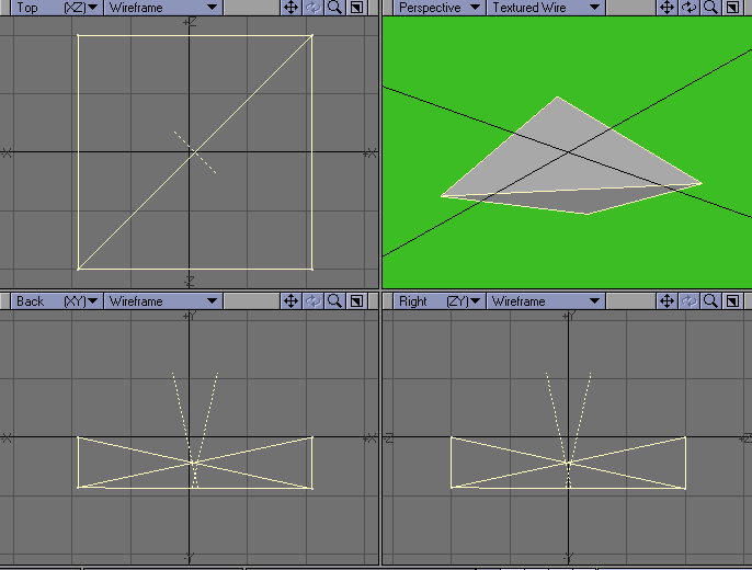
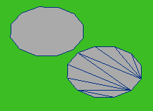
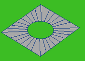
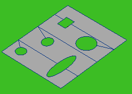
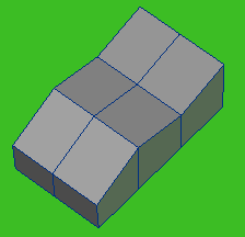
Let me give you some examples. I have created a simple button - in this first example with Nurbs - astute viewers will note that I Have used edge loops to control the radius of my edges in this Nurbs mesh. I could use point weighting to control these radii (sp?) but there is an inherent problem with that - if the mesh is to be used purely in Lightwave there will be no problems - but if exported for other applications (which invariably happens I guarantee you) then issues arise - point weighting does not translate well into 3rd party applications! Not to mention it doesn't behave properly when it comes to using catmull Clark within Lightwave itself. The weighting can and does result in very different effects - so although edge loops can add to the polygon count - it is mostly preferable.

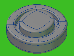
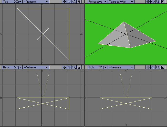
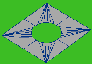
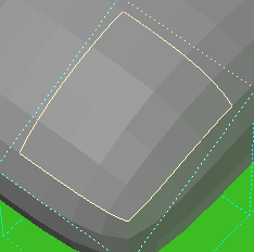
Now this is supposed to be a mechanical round button - it should not be left as a sub patch object for layout really as it will not deform - unless it 
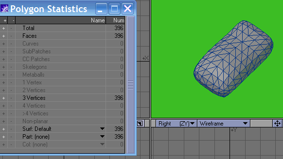
was say a rubber button - but it's not!  
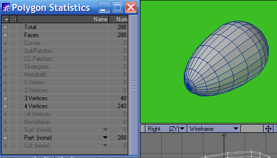
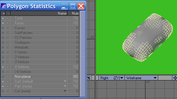
Now I have had to use a sub patch level of 8 to get rid of a noticeable level of faceting on a simple cage like this - and the result when frozen and tripled for rendering becomes:

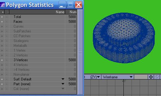
.. a whopping 5,888 polygons from an initial polygon cage of just 46 polygons!

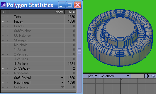
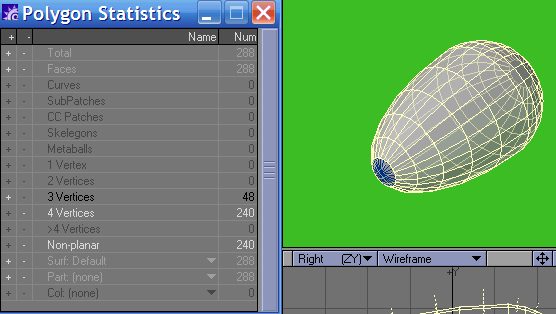
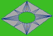
Now, in my pipeline I would, if I had used Nurbs to make this object; frozen and optimised it with bandglue and gotten something along these lines:

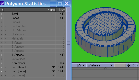
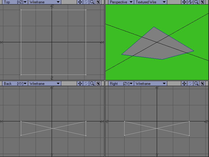
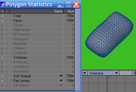
...so that's a saving of 4,448 polygons but you will note there are resultant non-planar's so I need to triple them:

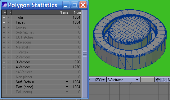
...the end result is 1,604 poly's and a saving of 4,284 for this button now when it comes to rendering; and the net result 
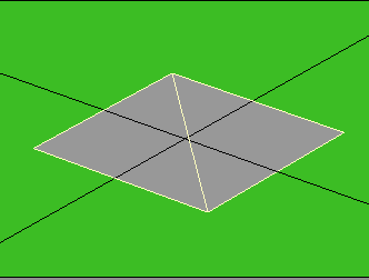
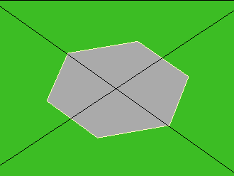
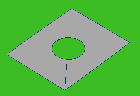
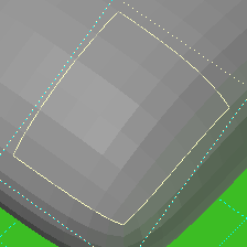
is it will render more or less exactly the same in appearance. However there is an issue we have not resolved yet and that is with a cage so low, we are not getting a perfectly round button! Look at this Top projection and you will see it more obviously.

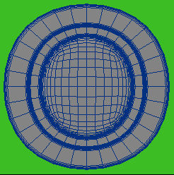
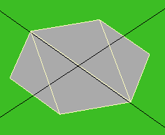
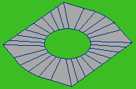
no, to get a more accurate approximation of a circular button we need more polygons to start with - more along these lines in fact...

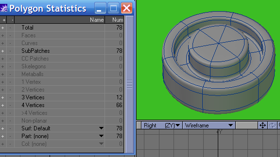
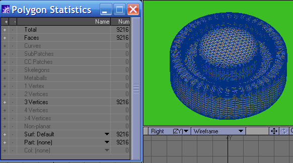
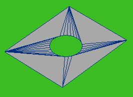
We now have a base cage of 78 polygons and this produces this many polygons when frozen and tripled, if left as a Nurbs cage for rendering:

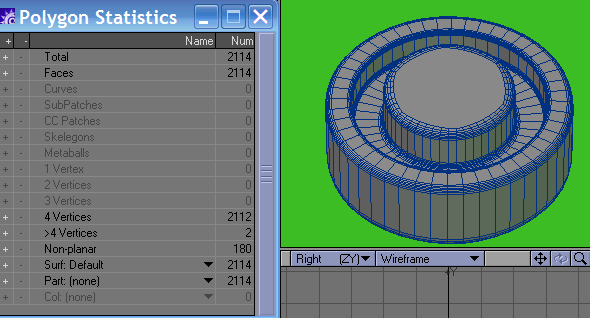
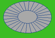
or this many when frozen and optimized and taking care of the non planar's in modeler prior to rendering.

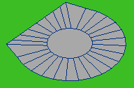
But you know what? Even though this is now a more accurate representation of a circular button it's still not perfectly circular! Plus the polygon counts for a simple button - even a highly detailed one -is too much - imagine 50 of these on your panel! ;o)

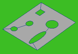
Lets' try a different tactic now shall we? Lets make it with the disc tool - some bevel ops' and rounder and see what happens?

a perfectly circular (well as circular as a 48 sided disc can be) button with nicely defined radius edges - looks better and comes in substantially less than even the frozen optimized version!

The lesson that needs to be learnt here is simple really - stop using Nurbs to create cylinders and boxes - even if they have rounded edges and rounded corners and the like - there are better tools for the job right there in the modeler toolbox!

If you have a mesh that has a weird body shape (world war two tank is a good example) make the base shape and freeze it! Then add details with Boolean, stenciling, rounder and Vertibevel if you have it in your arsenal - they are better suited to the job than Nurbs for adding that ancillary detailing and the polygon counts will be drastically lower - allowing you to add more rich detail instead. think about it.... 

Also when it comes to flatness or planarity - if your objects are mainly flat - even if you then rotate that object - it will still be a flat object - then don't worry about tripling or fanning by hand - let Lightwave take care of that for you - it only really becomes an issue with objects that are not flat to start with - keep an eye on the non planar's then and optimize to suit. Two of my other tutorials - the ones on optimizing meshes and smoothing will also be good reading and recommended.

Hopefully you have gleaned some understanding and some golden rules I hope from this short tutorial - these are accepted principles and practices in the real world of generic wide spectrum studio modeling. I hope you use them to good effect.

 Need help detailing your spaceships? Have to make a cityscape fast? Need to fill any area with random believable detail?

The Ultimate Greeble & Nurnie Collections will make light work of any of your Projects! Check them out now!

check out the ultimate nurnie collections!

Back to top