|
Rigging Hydraulic Pistons with IK in Lightwave
|
Rigging pistons with Inverse Kinematics has long been the bane of
artists in Lightwave. A long time ago someone came up with a formula for doing it and it
has been passed down through the ages! - I'm presenting this tutorial simply as a copy of
that long developed method so that people searching for the answers will always have some
sort of mirror for the technique to fall back on.
|
|
The First step in the process begins within modeler where will
construct the housing and the shaft for our hydraulic piston.
|
click for larger image in separate
window
|
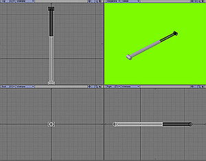
As you can see from the image I have constructed the housing and the
shaft along the Z axis in modeler. I have placed the housing in the first layer and the
shaft in the second layer. The next step we must do - purely to make our lives easier
within layout later - is to set the pivot point for our objects within
modeler.
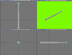
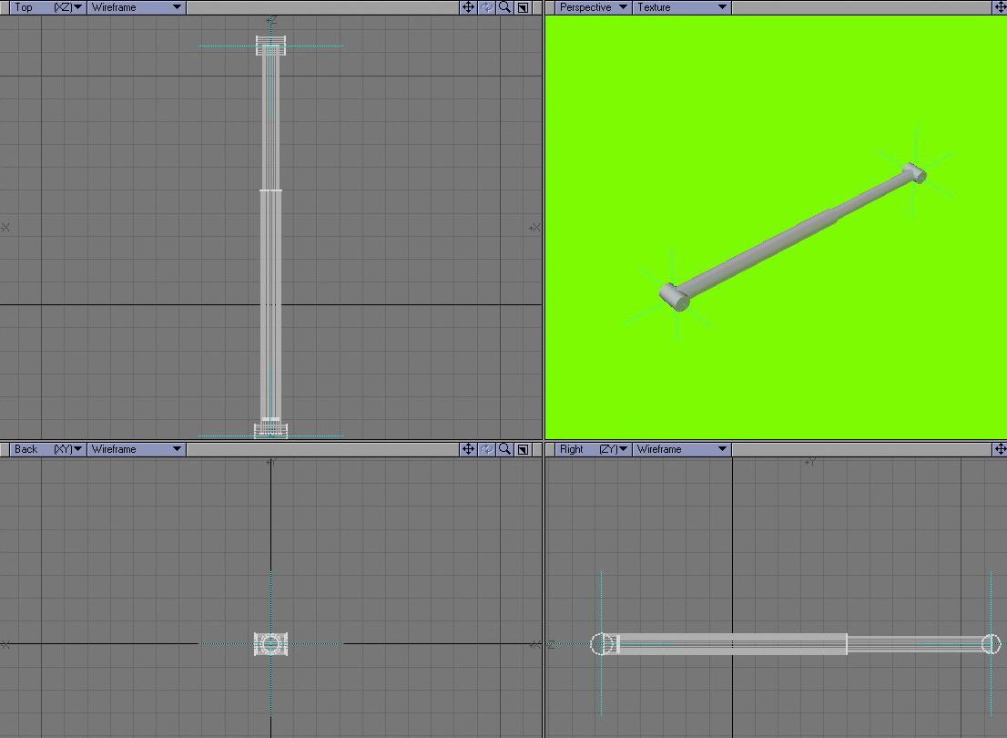
By using the view tab and the
Pivot button we can set the pivot point in the right/left
view port to the proper place for both our object layers - in the following example image
I have both layers selected to show you where your pivots should essentially be - i.e. at
the center of rotation of the what will be the fixed bases of your housing and shaft
sections.
|
click for larger image in separate
window
|
Now that we have our layers pivot points set it is time to take our
object into Layout for finalization of the rig. The first thing we do here is to create 4
NULL Objects and name them like so:
-
Housing base
-
Housing end
-
Shaft base
-
Shaft end
|
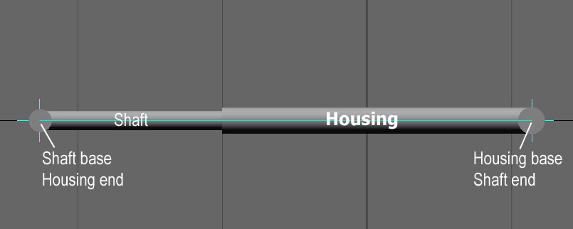
The nest step is the correct
positioning of our nulls - study the following diagram:
|
|
|
|
The shaft base and housing end Nulls are placed at the
pivot point for the Shaft ;and the Housing base and shaft end nulls are placed at the
pivot point for the Housing. The next step now is to ensure you have parent in place activated in the LAYOUT GENERAL OPTIONS & to
correctly set up the hierarchy of our piston setup.
|
The parenting must be done as follows:
The housing end is parented to the housing mesh and that then is
parented to the housing base null. Similarly for the shaft the shaft end is parented to
the shaft mesh and that then is parented to the shaft base. This diagram will make it a
bit clearer:
|
|
|
|
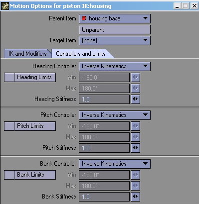
With parenting out of the way now we
can handle the IK settings to get it all to work. Select the Housing object and then open it's motion options panel. In the
Controllers and Limits tab set all the controllers to
Inverse Kinematics.
|
|
|
Do exactly the same for the Shaft object.
|
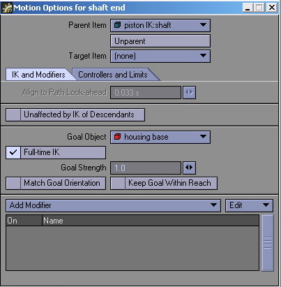
Nearly there now. Select the
Housing End Null and again set all the controllers to
Inverse Kinematics. Then select the IK
and Modifiers tab and clock on Full-Time IK and make
the Goal Object the Shaft Base
null.
Do exactly the same now for the shaft end null - but
this time make it's Goal Object the Housing Base null
|
|
|
|
And that's basically it - you're all done - if you now select either
of the base nulls and pull them around a bit you will see that the piston works as if by
magic the way it is intended to!
|
|
If you wanted to get this to work say
for an off ramp for a ship it's easy -- position your objects by manipulating the base nulls
and then parent the one base null to the ship and the other base null to the ramp. Then just
open the door around it's pivot and watch the struts work all by themselves just as
intended.
|
|
Need help detailing your spaceships? Have to make a
cityscape fast? Need to fill any area with random believable
detail?
The
Ultimate Greeble & Nurnie Collections will make light work of any of your Projects! Check them out now!

|

 Facebook
 Twitter